Structural Drafting: Taking the 3D visualisation to the next level
In Design and Innovation Issue #16 we talked about how Bligh Tanner makes use of 3D images to deliver an optimised project design experience. We established that this process provides:
- Clients and stakeholders an elevated visual interpretation of structural design to facilitate coordination
- A more comprehensive representation of the scope of a project and offer more accurate construction costing.
The process
The end product of a design is built from true views in the form of dimensioned 2D setouts on architectural and engineering drawings.
These drawings then make their way onto 2D (&3D) fabrication shop drawings and builders plans.
As a result of the Revit 3D modelling process, engineering construction drawings are now utilizing 3D details in conjunction with traditional 2D details.
The benefits
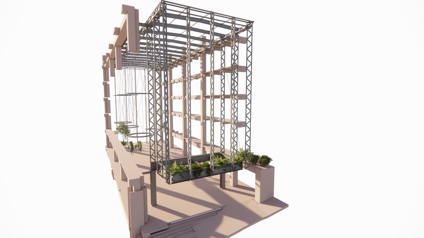
Notwithstanding the vast majority of simple sections and details of typical slabs, foundations and straight forward framing connections are traditionally detailed in 2D. We can now see typical details shown as 3D images making their way into project’s drawing documentation. There are also many cases where a structural connection is somewhat more complex, and so a second or third view is required to give the full picture of the design; this is where a 3D view can be of great benefit.
It cannot be stressed enough how much easier it is for stakeholders to grasp the design intent of a complex connection by looking at a 3D image of the finished product as opposed to only 2D views or an inadequate single view. Adding a single 3D view of a special connection or interface not only speeds up the interpretation of the final design, it also aids in the design and coordination process to produce more accurate and pleasing results.
The modelling of detail components such as steel plates and bolts in 3D is not necessarily a double up of work, as the components will also be shown from any 2D detail view. Furthermore, design refinements of said components will only save time as the change is reflected in all other views. Such fine tunings may in fact result in better outcomes, less RFI’s and potential cost savings.
Annotations and dimensions are no doubt better off shown in 2D representations, however the 3D modelling and presentation of both typical details and bespoke connections over and above the standard requirements of LOD300 is ultimately adding value for both Bligh Tanner and for our clients.
